
In this blog we will be discussing about Sub Transport Node Profile & Sub cluster concept in VMware NSX.
Before we start this discussion, Let’s re-visit Transport Node Profile, what exactly it is & why we use TNP ?
So, TNP is used to prepare an ESXi cluster for NSX, it is used as an template to prepare similar configuration across multiple clusters, which makes NSX configuration scalable & error free, since we need not to provide all inputs like uplink profile, IP pools , transport zones & uplink mapping for each cluster, we can simply prepare one TNP & map it to all clusters.
There is a ask for Host TEP pool while preparing TNP, In bigger environments where we have multiple cluster spanned over underneath separate Racks, each rack having their own L2 Networks, or stretched clusters across two different datacenters, where only management VLAN is stretched but not TEPs.
In those scenarios, if we want to use TNP two options comes in picture.
- Create L2 stretch for TEP VLAN across racks or physical DCs, which might not be feasible for every case.
- Use Sub TNP profile & Sub Cluster feature which is available in latest NSX 4.x, where your single cluster can have TEP IPs from different VLAN/Pools only condition is there should be L3 reachability among those VLAN.
So, in this approach Each rack ESXi’s can have L2 VLAN as their host TEP.
Lets explore this option in LAB, here i am going to use a bigger IP pool & going to split it into other 2 subcluster IP pool, then we will prepare 1 node with first sub-cluster IP pool & other 1 node with subcluster IP pool & remaining 2 nodes with parent TEP IP pool, so we are going to prepare 4 nodes cluster with 3 different TEP pools.
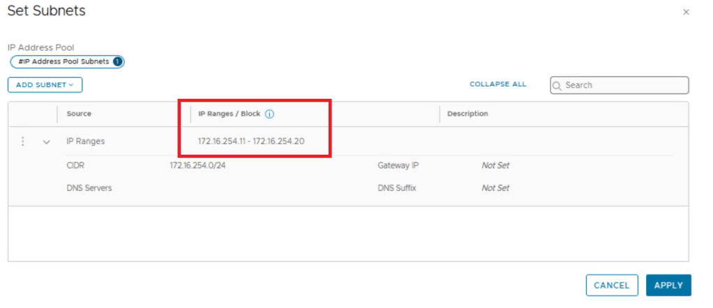
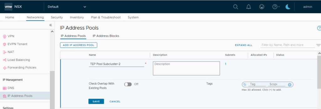
Lets create all 3 TEP pools first:
TEP pool 172.16.254.11 – 172.16.254.20
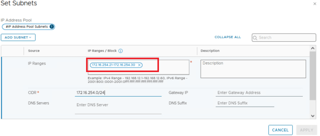
TEP pool Subcluster-1 172.16.254.21 – 172.16.254.30
TEP pool Subcluster-2 172.16.254.31 – 172.16.254.40


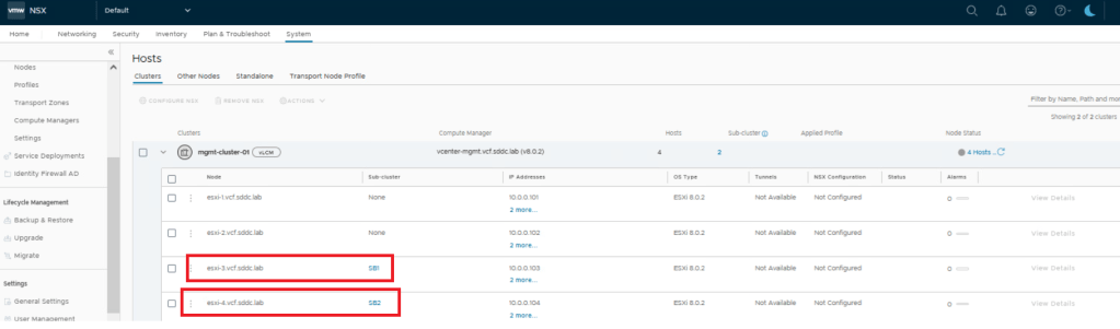
Below is the 4 node cluster we will be preparing for NSX today.

Since we are going to use 2 subcluster profile, it is required to use sub-cluster configuration on parent cluster, shown below, In actual scenarios 1 sub cluster would be part of same Rack using its own L2 VLAN for TEP configuration.
Now lets have a look to transport node profile & sub TNP configuration there.

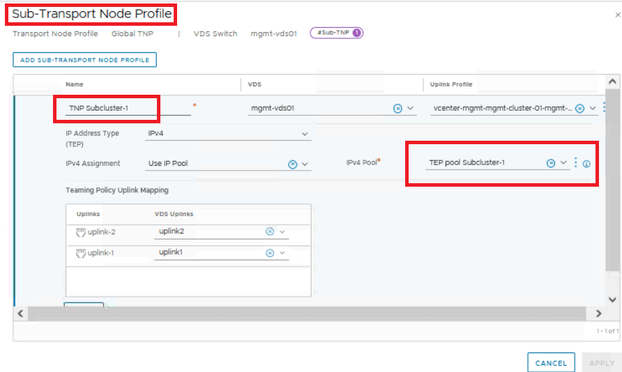

Once Sub TNP configuration is done with using different IP pools, its time to map the profile to cluster to install NSX over it.
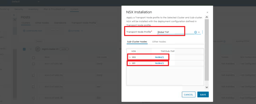
While installation we get an option to map Sub-TNP to Sub-Clusters.
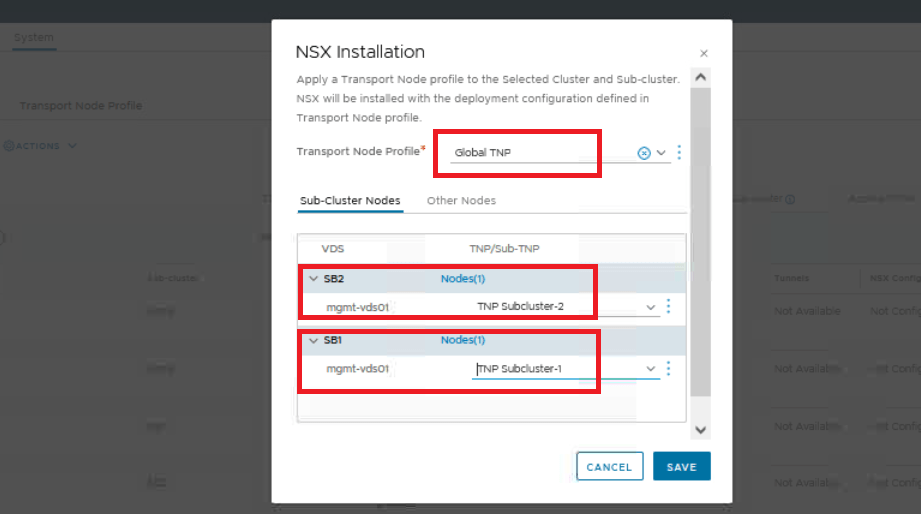
Here i have mapped Subcluster-1 having single node to TNP-Subcluster-1, & Subcluster-2 again having single node to TNP-Subcluster-2 that is these nodes will take TEP IPs from respective IP pool.
remaining 2 nodes of the cluster will take TEP IP from main / Parent TEP pool.
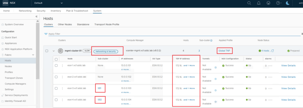
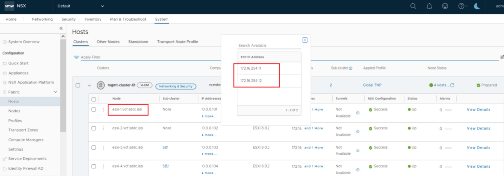
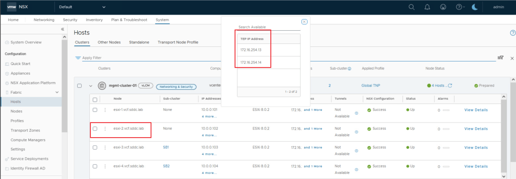
We can see in above screenshots that ESXi-1 & ESXi-2 has taken TEP IP from parent TEP pool which was having range 172.16.254.11 – 172.16.254.20
Lets validate SB-1 & SB-2 now.


ESXi-3 which was part of Sub-Cluster-1 has taken IP from its respective IP pool having range 172.16.254.21 – 172.16.254.30
Similarly ESXi-4 which was part of Sub-Cluster-2 has taken IP from its respective IP pool having range 172.16.254.31 – 172.16.254.40
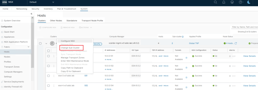
Now lets test one more piece, lets make ESXi-1 part of Sub-Cluster-1, expectation is it should change its TEP IPs from parent TEP pool to Sub-cluster-1 TEP pool.

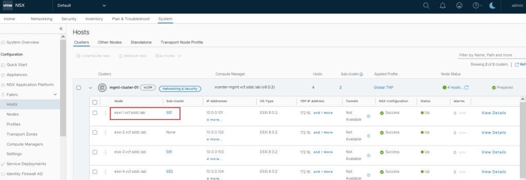

TEP IPs for ESXi-1 has change to Sub-cluster-1 TEP pool now.
This is it for today’s blog, we will discuss some new topic in upcoming blogs, stay tuned… !!
—–Thank You—–
Prashant Pandey
