
Recently I have completed one of the deployments with VRF-Lite having 10 tenants, VRF-Lite is such a useful feature to achieve multitenancy in NSX-T Data Center.
For this document and topology simplicity, I have kept the tenant count as 2 only but the concept is same for any number of tenant count.
I have decided to capture the concepts in 2 different blogs –
Part-1 – will be focusing on VRF-Lite concepts discussion & configuration.
Part-2 – we will be performing Route-Leak among 2 different VRF-Lite.
VRF-Lite – Introduction
- VRF lite feature got introduce with NSX-T 3.0 onwards to support multitenancy environment.
- It allows us to have segmentation among different tenants, without having the need of multiple Tier-0 & Edge nodes.
- Resource saver, as it allows us oversubscription.
- Logical routing isolation is provided in NSX and to external peers.
Requirements
- Tier-0 must be deployed & configured with uplink interfaces.
- External connectivity with L3 peer with support of VLAN tagging.
Multi-tenancy with and without VRF-Lite
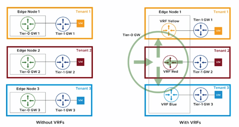
Above diagram has taken from design document for easy reference.
Point to be Noted
- Overall throughput of Edge Node participating in VRF-Lite configuration, will be same only, however we can configured 100 VRF-Lite instances per edge node, Reference – (https://configmax.esp.vmware.com)
- Best fit for VRF Lite is – logical separation requirement, where network oversubscription is acceptable.
Use-Case
- Allow same network Address to coexist in different RD.
- Run multiple routing instance on same gateway to optimize existing resources.
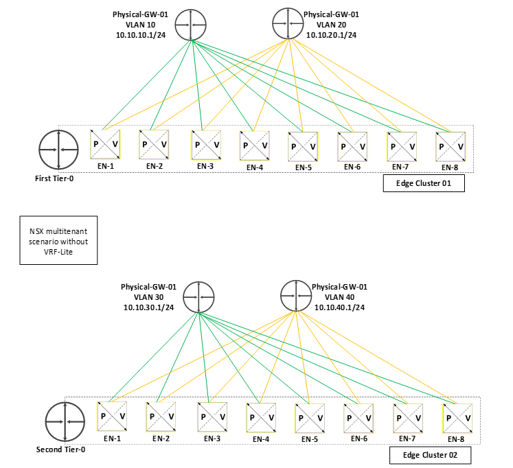
Tier-0 to Physical peering in multitenant scenario
Without VRF-Lite
- We need separate Tier-0 for each tenant.
- We need separate Edge Nodes / Edge Clusters for each tenant, which is going to consume hell of resources if our tenant counts increase.
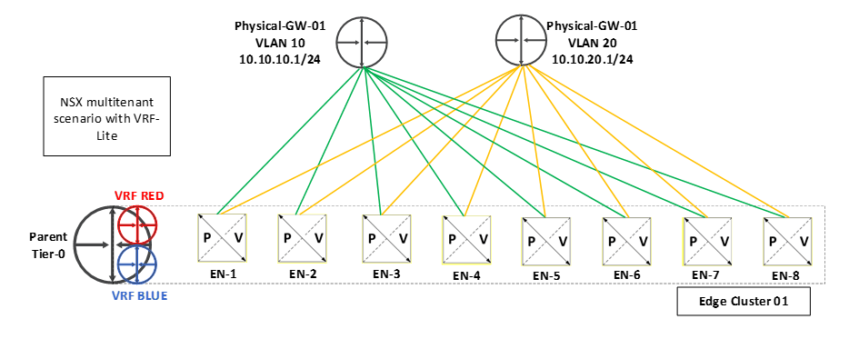
With VRF-Lite
- We only need 1 Parent Tier-0, we can have multiple VRF gateways under the same. (As per max config data it is 100 VRF per Edge Node for NSX 3.2 version)
- We no longer need separate Edge Nodes, same ENs will be used for all VRF.
- Here both VRFs are using same edge nodes for their respective VRF.
- Parent Tier-0 is still usable & act as separate router.
==============================================================================================================
Lets talk about the steps to configure VRF-Lite. Below is the topology which we are going to discuss in this blog.
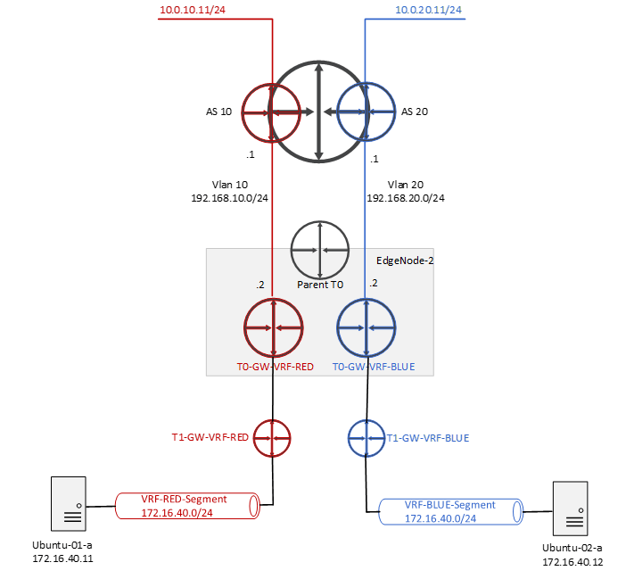
1. Create the Uplink Trunk Segment – VLAN 10 for VRF-RED , VLAN 20 for VRF BLUE
Networking > Connectivity > Segments > NSX> Add Segment

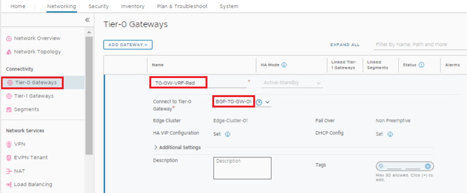
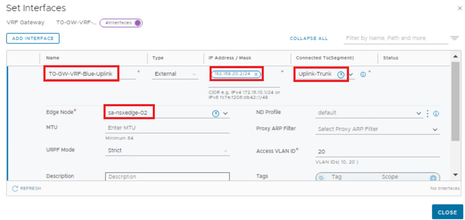
2. Deploy and Configure the VRF Gateways
- Create first VRF named – T0-GW-VRF-RED
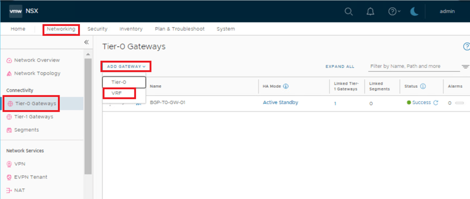


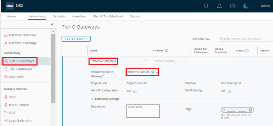
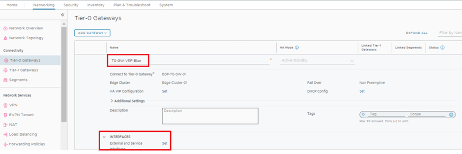
- Create second VRF named – T0-GW-VRF-BLUE

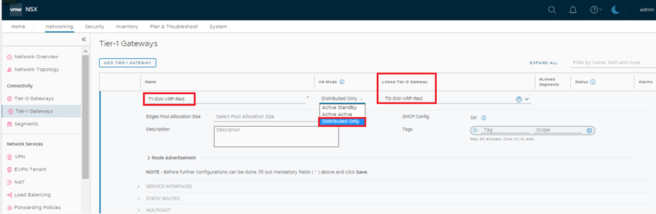
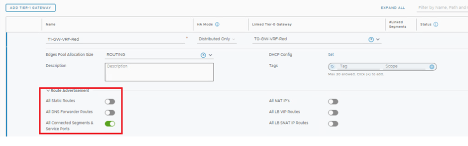
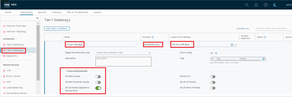
3. Deploy and Connect the Tier-1 Gateways to the VRF Gateways
Networking > Connectivity > Tier-1 Gateways> ADDTIER-1 GATEWAY
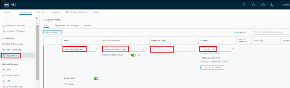
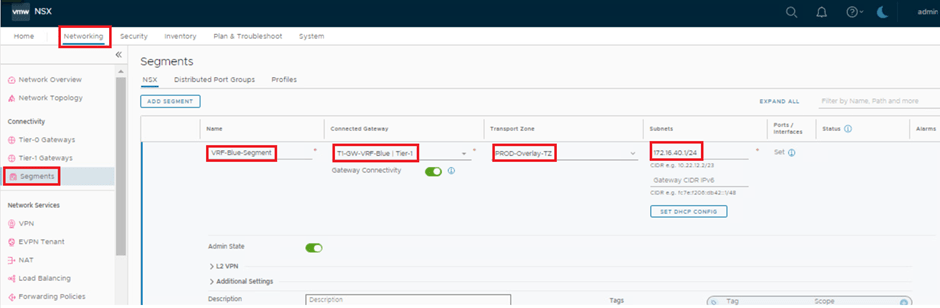
4. Create and Connect Segments to the Tier-1 Gateways.
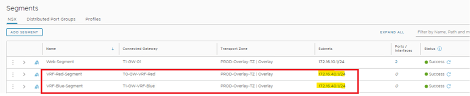
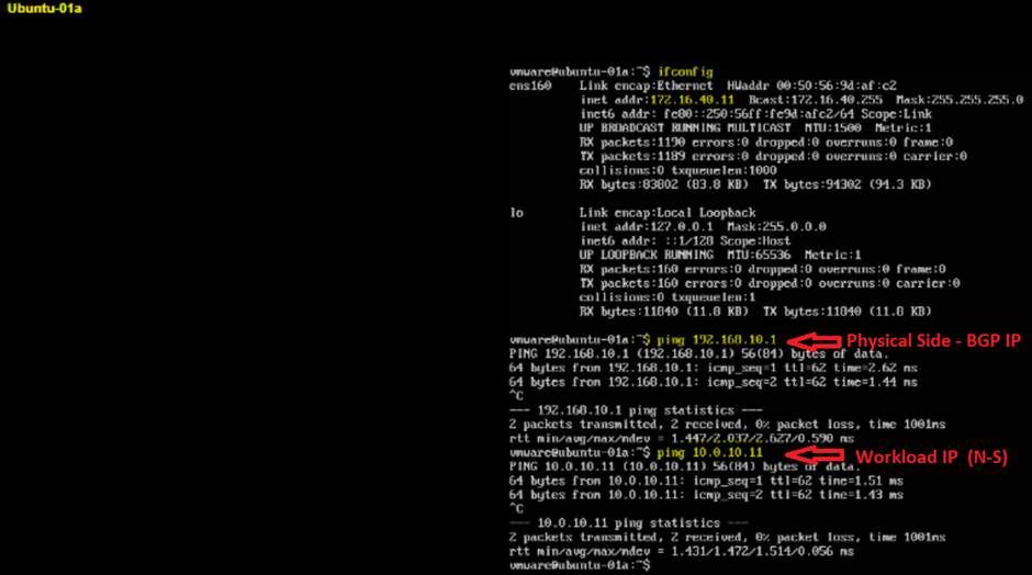
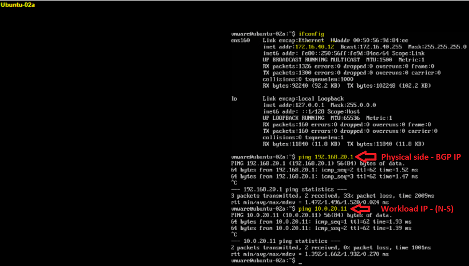
5. Attach VMs to Segments on Each VRF and Test the VRF End-to-End Connectivity.
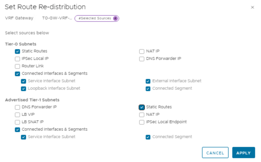
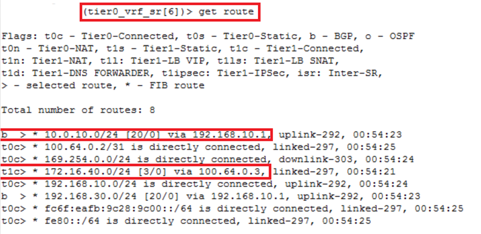
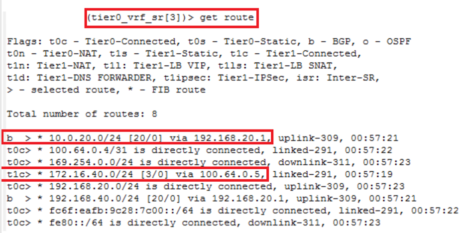
6. Let’s Review the Routing Tables in Each VRF.
This is it for today’s blog. We will be discussing & configuring “Route Leak between both VRFs” in next blog, Stay tuned…
PS: Any Improvement points or suggestions are welcome.
—–Thank You—–
Prashant Pandey
